Beranda
/ Ic 4017 Led Circuit Diagram / Disco Led Lights Circuit Using Ic 555 Gadgetronicx : A number of different chser circuit are covered under this post, which.
Ic 4017 Led Circuit Diagram / Disco Led Lights Circuit Using Ic 555 Gadgetronicx : A number of different chser circuit are covered under this post, which.
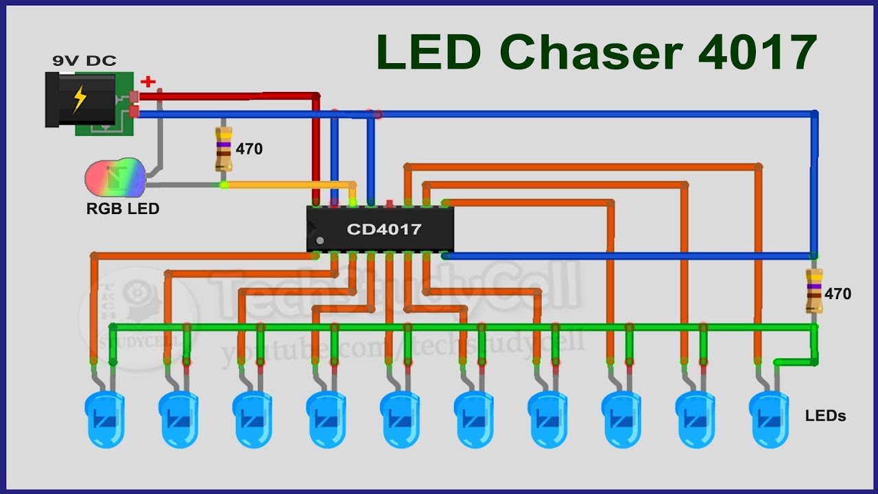
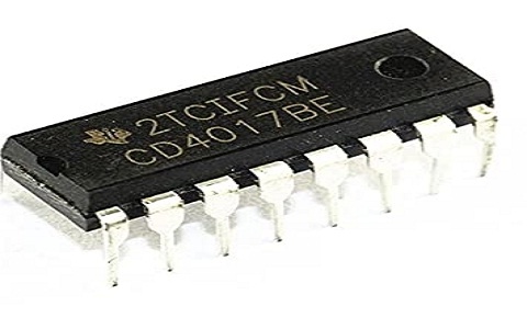
Ic 4017 Led Circuit Diagram / Disco Led Lights Circuit Using Ic 555 Gadgetronicx : A number of different chser circuit are covered under this post, which.. By this we can change the led chasing speed. Create circuit diagram with ease. Jan 11, 2021 · to make this simple led chaser circuit i have used only a 4017 ic. But for instance, the hef4017 recommends only up to 15v. The cd4017 is a very common ic, so you should be able to find it in one of the online stores.
It stays high for 5 clock pulses, then goes low again. The cd4017 is a cmos decade counter ic. Connect this pin to t. Here is the one we made in our lab. Clock enable (13th pin) is an active low input, so it is connected to ground.
Led Chaser Circuit With Pcb Layout Running Lights Eleccircuit Com Simple Electronic Circuits Circuit Electronics Basics from i.pinimg.com This clock signal goes into the clock input of the ic 4017. Circuit diagram of 2 way 12 led running lights using cd4017 and ne555 which its output glowing will slide down each position, by begin from output at 1 is pin 3, 2, 4, 7, 10, 1, 5, 6, 9 and 11 in sequence. You can easily understand the working of the circuit from the above animation. It seems we missed this one of the most popular applications of the ic 4017. You can see that for each high pulse output of 555, the output of 4017 is incrementing by one. output frequency of 555 astable is given by the following equation. Connect this pin to t. This the schematic of the 10 led chaser with only 4017 ic. I already discussed about 10 led flasher circuit using single 4017 ic and 555 timer.
But the functionality and the pins are the same.
Here you can see the top and bottom view of the pcb design. Circuit diagram of 2 way 12 led running lights using cd4017 and ne555 which its output glowing will slide down each position, by begin from output at 1 is pin 3, 2, 4, 7, 10, 1, 5, 6, 9 and 11 in sequence. If your local electronics store doesn't have any of these chips, check out my list of online storesfor other places to buy from. A simple led chaser hobby circuit can be made using 555 timer and cd4017counter ic. You can remember it by thinking of a decade in years, which is tenyears. Circuit diagram of led chaser to make this simple led chaser circuit i have used only a 4017 ic. Every time the clock input goes high, the counter in the 4017 increases, which makes the next output high. I already discussed about 10 led flasher circuit using single 4017 ic and 555 timer. The output frequency of the 555 timer is determined by the resistors r1 rv1 and capacitor c1. This the schematic of the 10 led chaser with only 4017 ic. One 555 timer ic for provide the pulse frequency to flashing. Here the flashing rgb led will generate the clock pulse for cd4017 ic. You can use this circuit for decorative purposes.
But for instance, the hef4017 recommends only up to 15v. Create circuit diagram with ease. Leds are connected to each of the outputs and therefore appear to be "running" along a line. Create circuit diagram with ease. You can download the pdf files of pcb at the end of this article.
How To Make Led Chaser Circuit With Only 4017 Ic Youtube from i.ytimg.com The clock (clk) pinincreases the counter with one every time the pin goes from low to high. Edrawsoft.com has been visited by 10k+ users in the past month Then connect the output of it into a cd4028. That circuit was used to only 10 led operation. Resistor r3 is used for current limiting. Connect each to a resistor and led if you want to see pins change state. The counter circuit in the cd4017 however, is not a standard ring counter. One 555 timer ic for provide the pulse frequency to flashing.
How many leds in ic 4017 led chaser circuit?
Where does clock signal go on ic 4017? It's very common that a counter will give you the output in binary form. And also use to build all kinds of the timer, led sequencers and controllers circuits. This is a two ways of led running lighting. This has to do with the manufacturer of the chip and the technology used. But the output from the decade counter in the cd4017 is decoded, meaning that it will set one of the output pins (q0 to q9) high corresponding to the counter value. Two 4017 counter ic to get sequenced output from it. This is also known as a ring counter. You can easily understand the working of the circuit from the above animation. As i explained above, 555 timer is wired as an astable multivibrator. Circuit diagram of led chaser to make this simple led chaser circuit i have used only a 4017 ic. One of the most popular hobbyist projects to build with this chip is the running leds circuit. Then connect the output of it into a cd4028.
See full list on electrosome.com By this we can change the led chasing speed. But the functionality and the pins are the same. See full list on electrosome.com This is also known as a ring counter.
Ic 4017 Decade Counter Pin Configuration Its Applications from www.elprocus.com Edrawsoft.com has been visited by 10k+ users in the past month The output pins q0 to q9goes high one by one as the counter increases. Here the flashing rgb led will generate the clock pulse for cd4017 ic. It's very common that a counter will give you the output in binary form. Led d1 is used to indicate the output of 555 ic and the resistor r3 is for current limiting. Decoding and control are by 16 inverters and 15 gates. You can see that for each high pulse output of 555, the output of 4017 is incrementing by one. output frequency of 555 astable is given by the following equation. Every time the clock input goes high, the counter in the 4017 increases, which makes the next output high.
But for instance, the hef4017 recommends only up to 15v.
Connect this pin to t. Usually with a few extra characters at the end (ex: Resistor r3 is used for current limiting. Leds are connected to each of the outputs and therefore appear to be "running" along a line. But the functionality and the pins are the same. A 555 timeris set up in astable mode, which makes it into an oscillator circuit that creates a clock signal. Edrawsoft.com has been visited by 10k+ users in the past month This is a two ways of led running lighting. You can easily understand the working of the circuit from the above animation. Output frequency = 1.44/((r1 + 2rv1) * c1) so you can easily change the output frequency of above circuit by varying the preset rv1. One of the most popular hobbyist projects to build with this chip is the running leds circuit. Then connect the output of it into a cd4028. That circuit was used to only 10 led operation.
Berbagi
Posting Komentar
untuk "Ic 4017 Led Circuit Diagram / Disco Led Lights Circuit Using Ic 555 Gadgetronicx : A number of different chser circuit are covered under this post, which."

Posting Komentar untuk "Ic 4017 Led Circuit Diagram / Disco Led Lights Circuit Using Ic 555 Gadgetronicx : A number of different chser circuit are covered under this post, which."